ATXA guide
1. Introduction
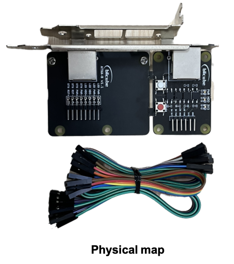
ATXA is an ATX adapter borad to manage the power of your computer. The product includes two modules A-board and B-board. A-board is connected to the Raspberry Pi, B-board is connected to the computer's motherboard, and A-board is connected to B-board through a network cable.Join to the Discord Community Chat for news, questions and support!
| ATXA_A | ATXA_B |
|---|---|
 |
 |
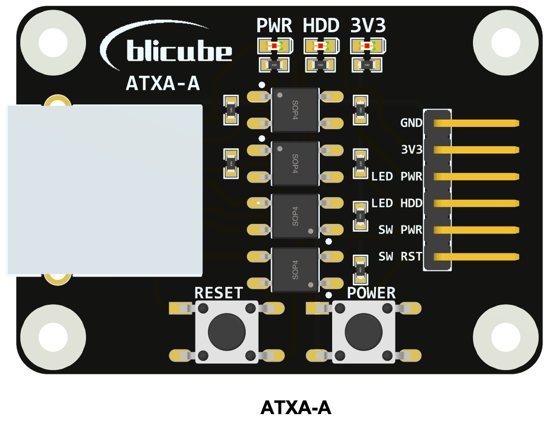
2. A-board
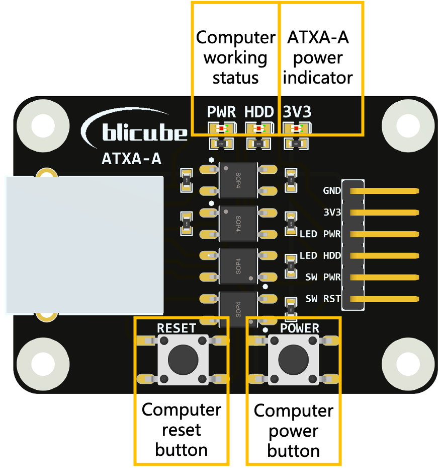
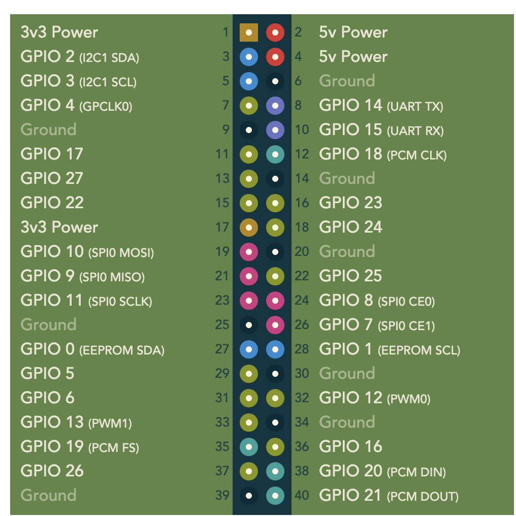
A-board is connected to the Raspberry Pi. The following table is a typical connection method in BLIKVM and PiKVM application.
| A-board | RPI4 |
|---|---|
| GND | GND |
| 3V3 | 3V3 |
| LED PWR | GPIO24 |
| LED HDD | GPIO22 |
| SW PWR | GPIO23 |
| SW RST | GPIO27 |
 |
 |
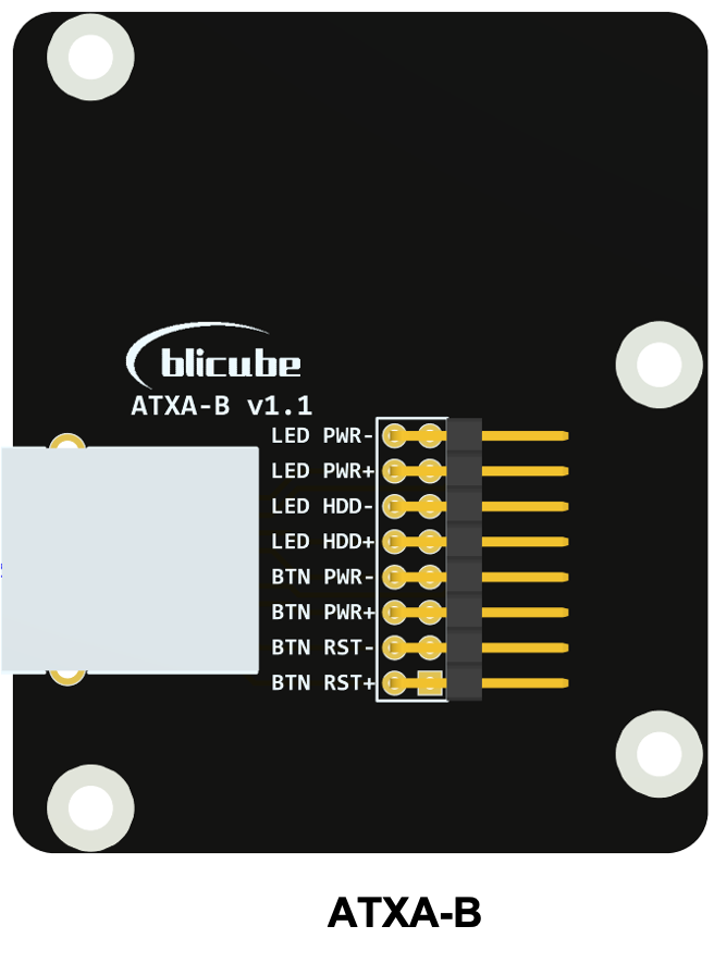
A-board is connected to B-board through a network cable. The following table is the corresponding relationship between the pin status of A-board and B-board.
| Pins on A-board | Pins on B-board |
|---|---|
| LED PWR is HIGH | LED PWR+ is HIGH, LED PWR- is LOW |
| LED PWR is LOW | LED PWR+ is LOW, LED PWR- is LOW |
| LED HDD is HIGH | LED HDD+ is HIGH, LED HDD- is LOW |
| LED HDD is LOW | LED HDD+ is LOW, LED HDD- is LOW |
| SW PWR is HIGH | BTN PWR+ and BTN PWR- connected, the power button is pressed |
| SW PWR is LOW | BTN PWR+ and BTN PWR- disconnected, the power button is unpressed |
| SW RST is HIGH | BTN RST+ and BTN RST- connected, the reset button is pressed |
| SW RST is LOW | BTN RST+ and BTN RST- disconnected, the reset button is unpressed |
3. B-board
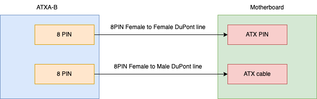
The b-board has an adapted full-height and half-height metal PCI mounting plate, which can be installed on the computer case. The user connects the pins on the B-board to the ATX control interface on the computer motherboard using the color DuPont cables provided with the product.
ATXA-B与电脑主板连接说明
根据电脑主板说明,首先找到主板上ATX功能相关引脚位置,拔下主板已经接好的ATX线,拔下后电脑的电源按钮将失去作用。ATXA-B主板共有两排8PIN引脚,两排引脚功能完全相同使用时无需区分。其中一排引脚用于KVM控制ATX相关功能,另一排引脚接主板上拔下来的ATX杜邦头,保持原有机箱电源按钮功能。根据主板和ATX-B上的具体引脚定义进行每根线的连接,连接关系可以参考下图:
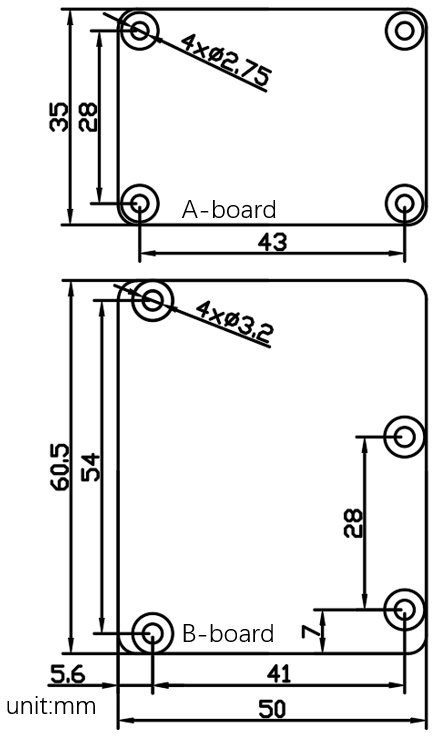
4.Mechanical Diagram
5.Test video
youtube:ATX
6.More link
Purchase:ATX
Created: June 5, 2022