BLIKVM PCIe CM4 Installation Guide
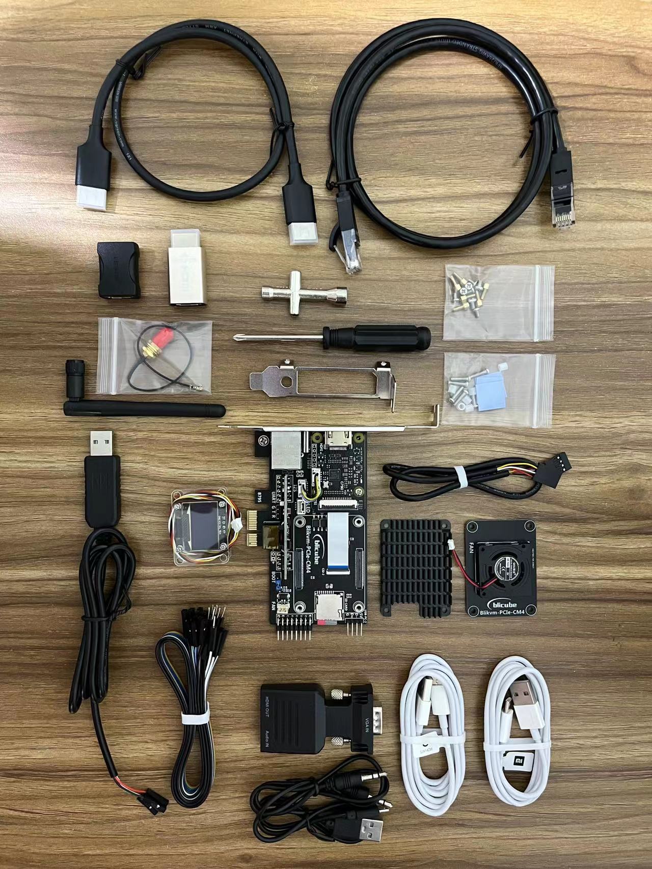
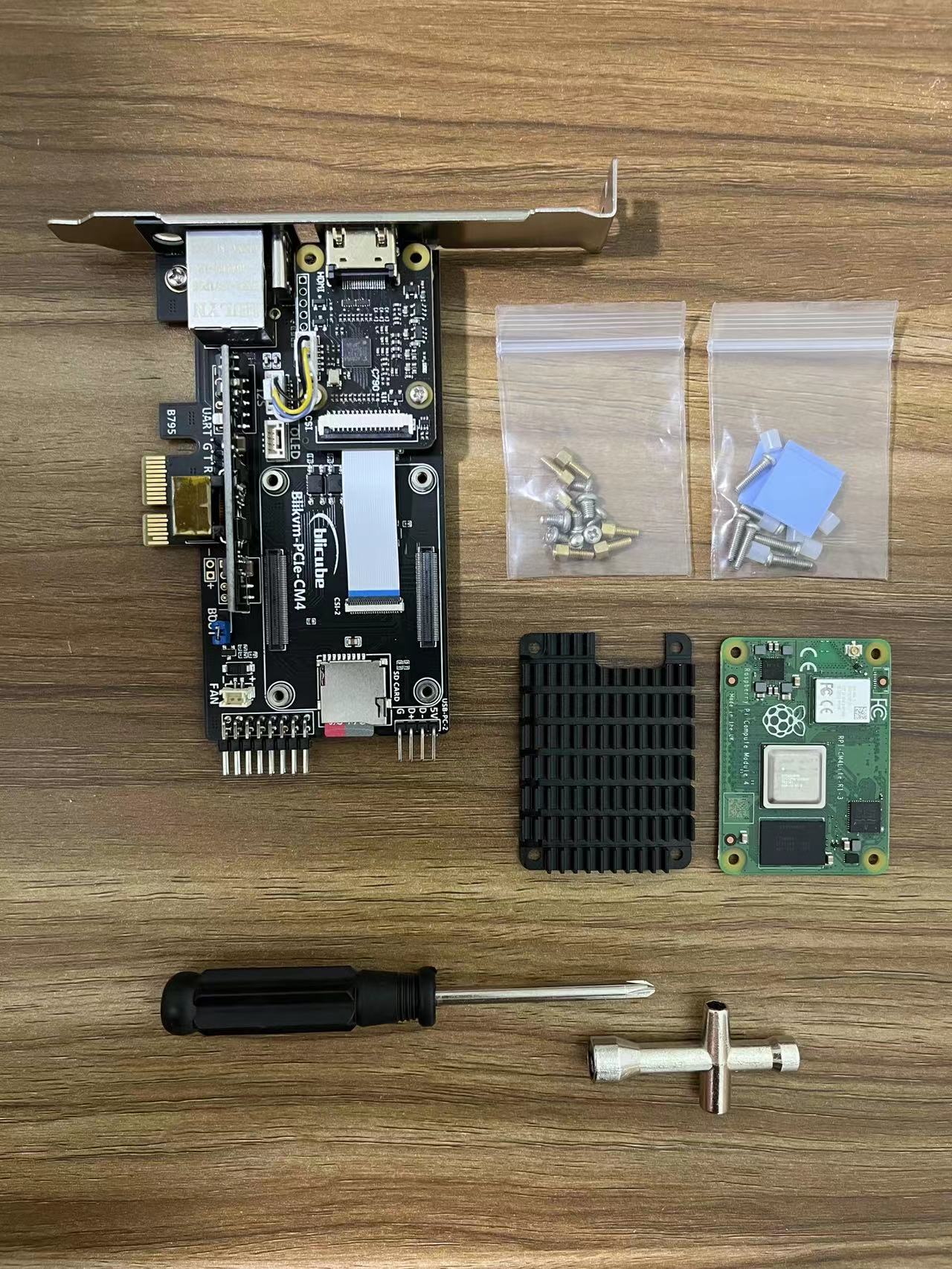
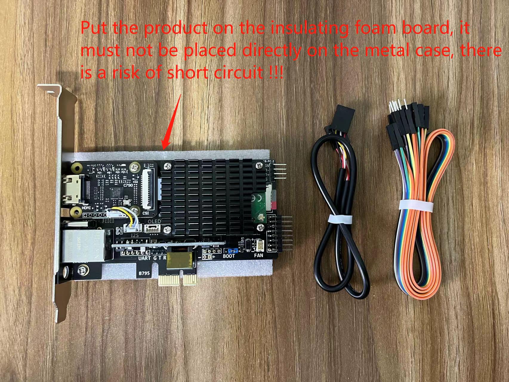
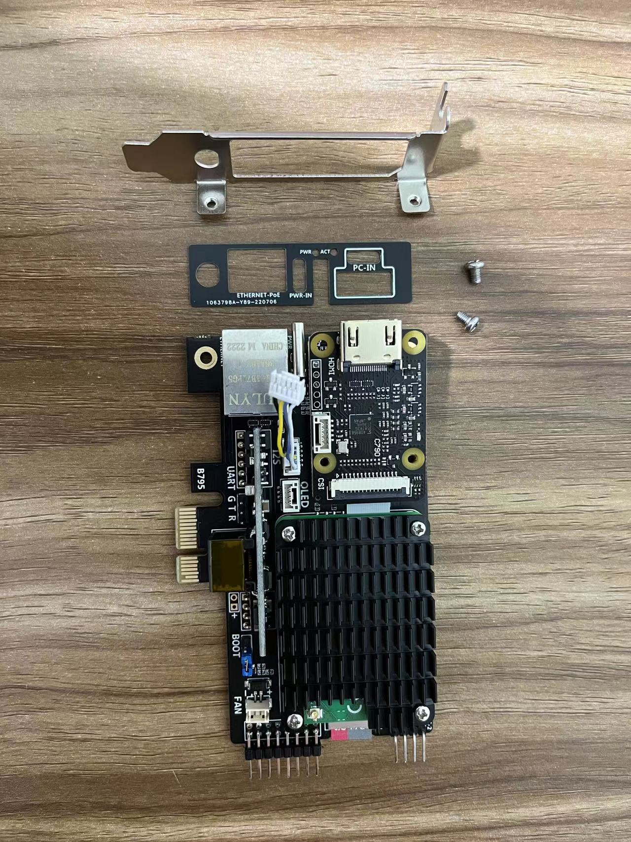
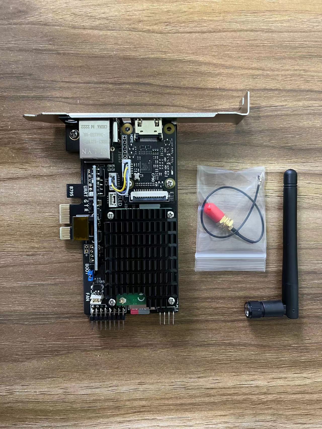
1. Unpack and take out the devices
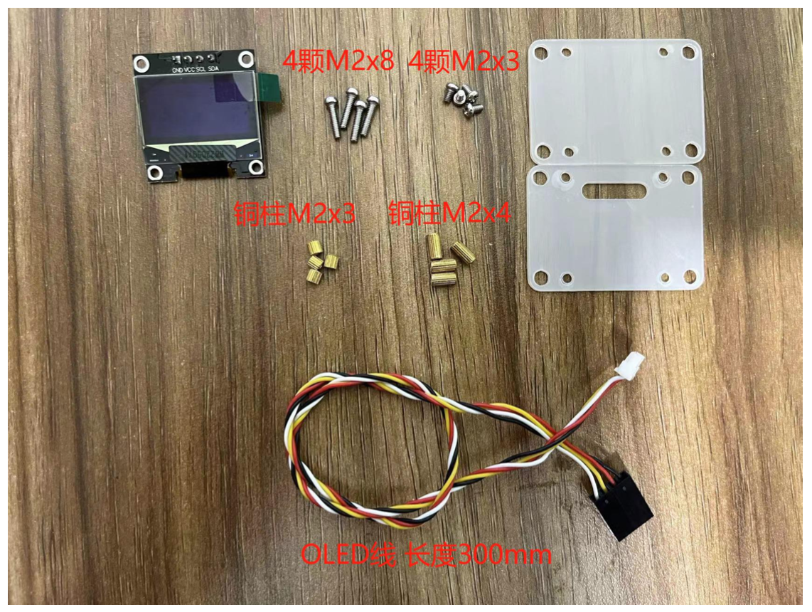
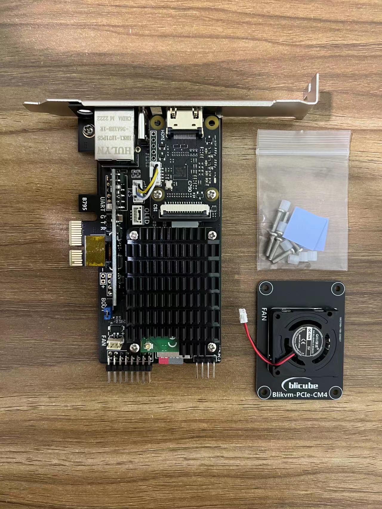
Product List
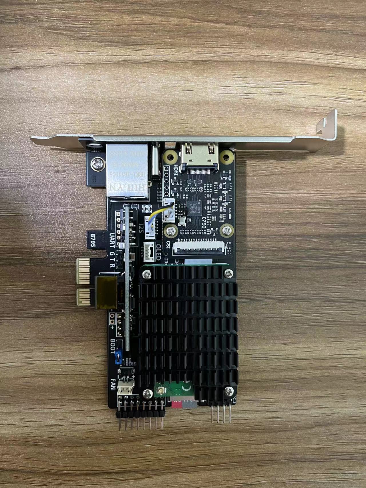
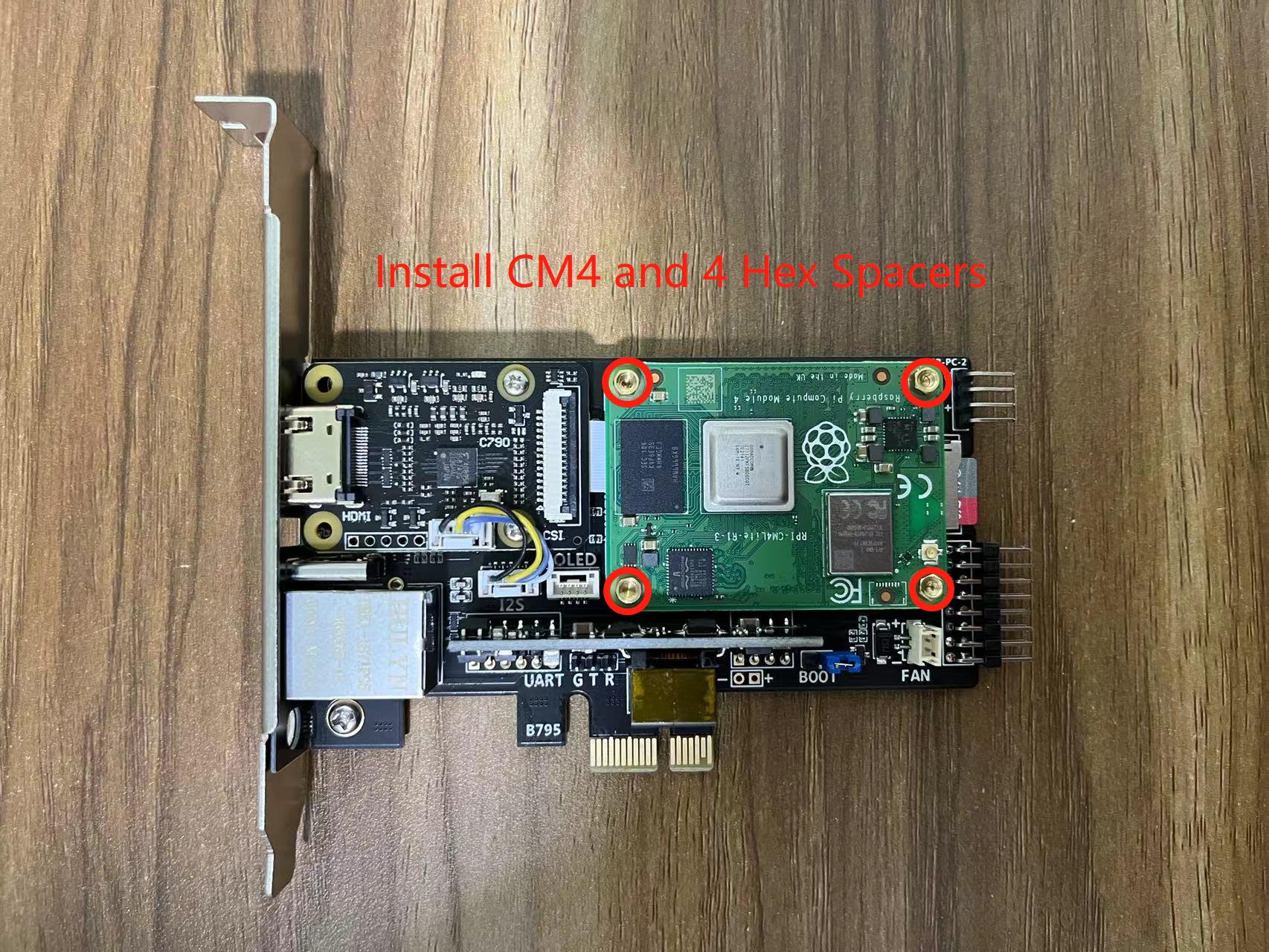
2. Install the main device
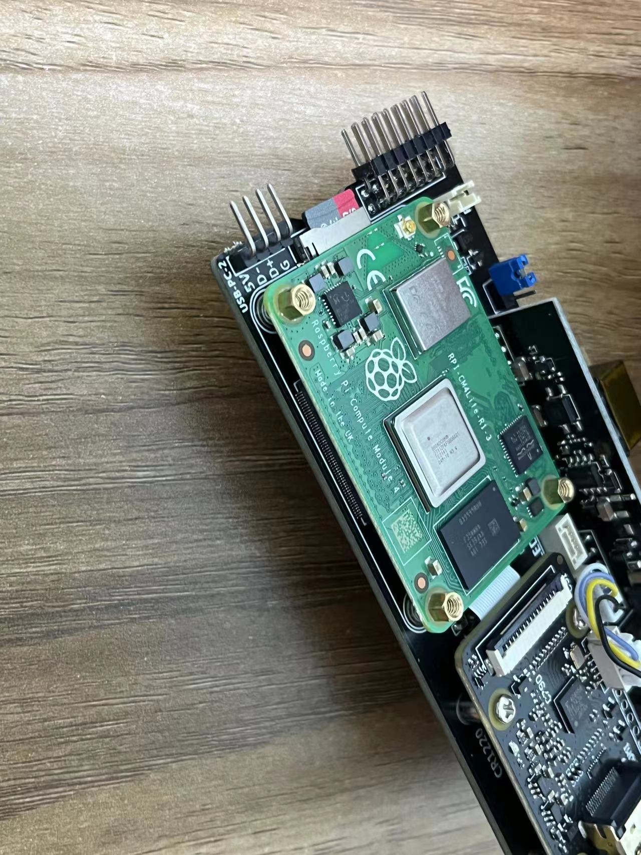
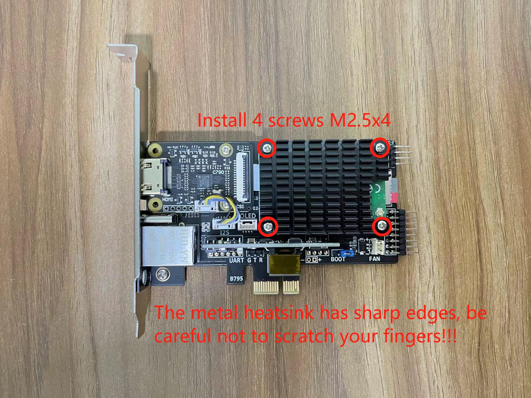
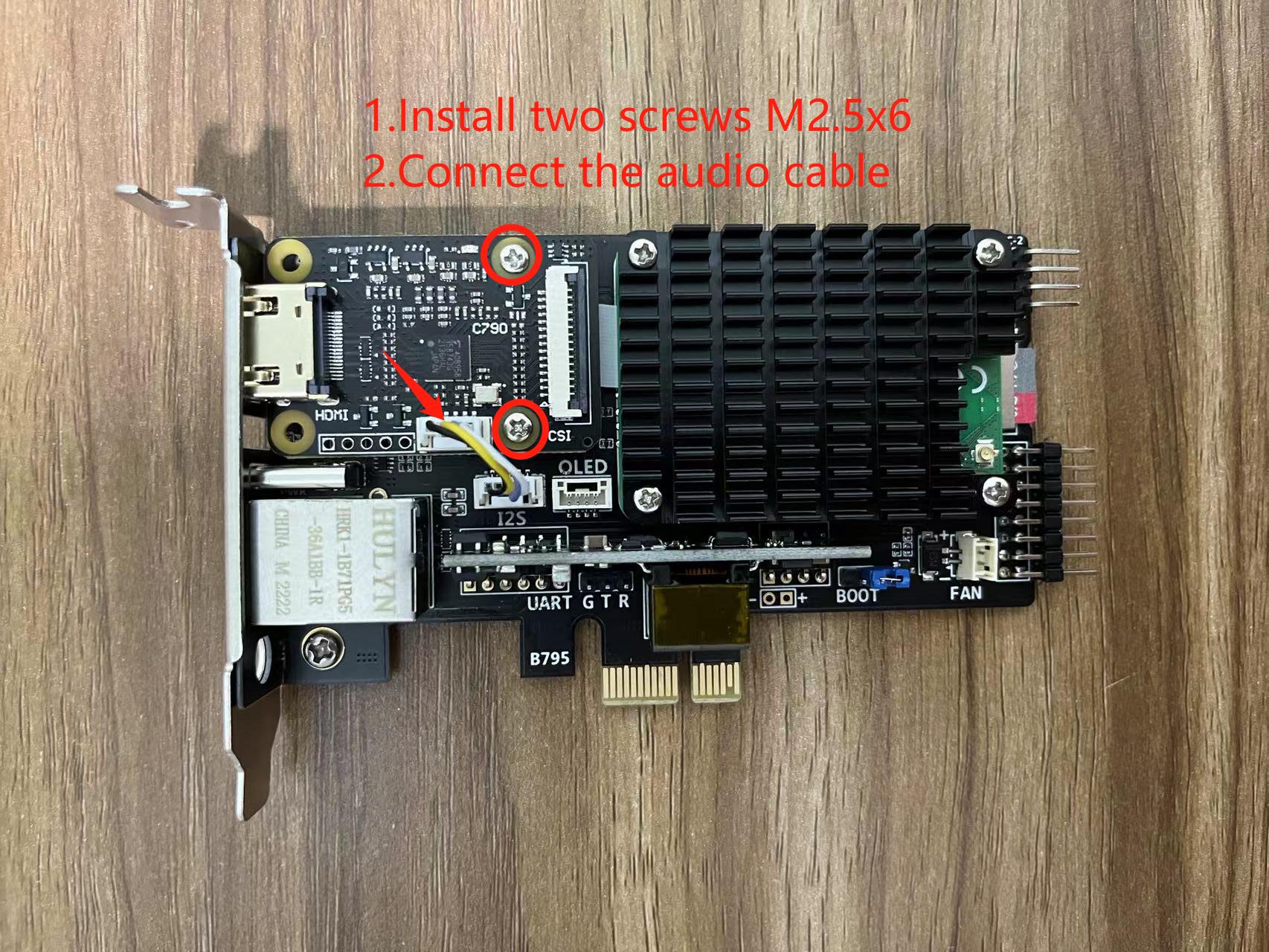
Install CM4 and 4 Hex spacers (This article takes CM4 lite as an example, using the image in the Micro SD card, CM4 eMMC user need to burn the image by yourself.)Stick a heat conductive sheet on the top of CM4 , tear off the protective film of the sheet.
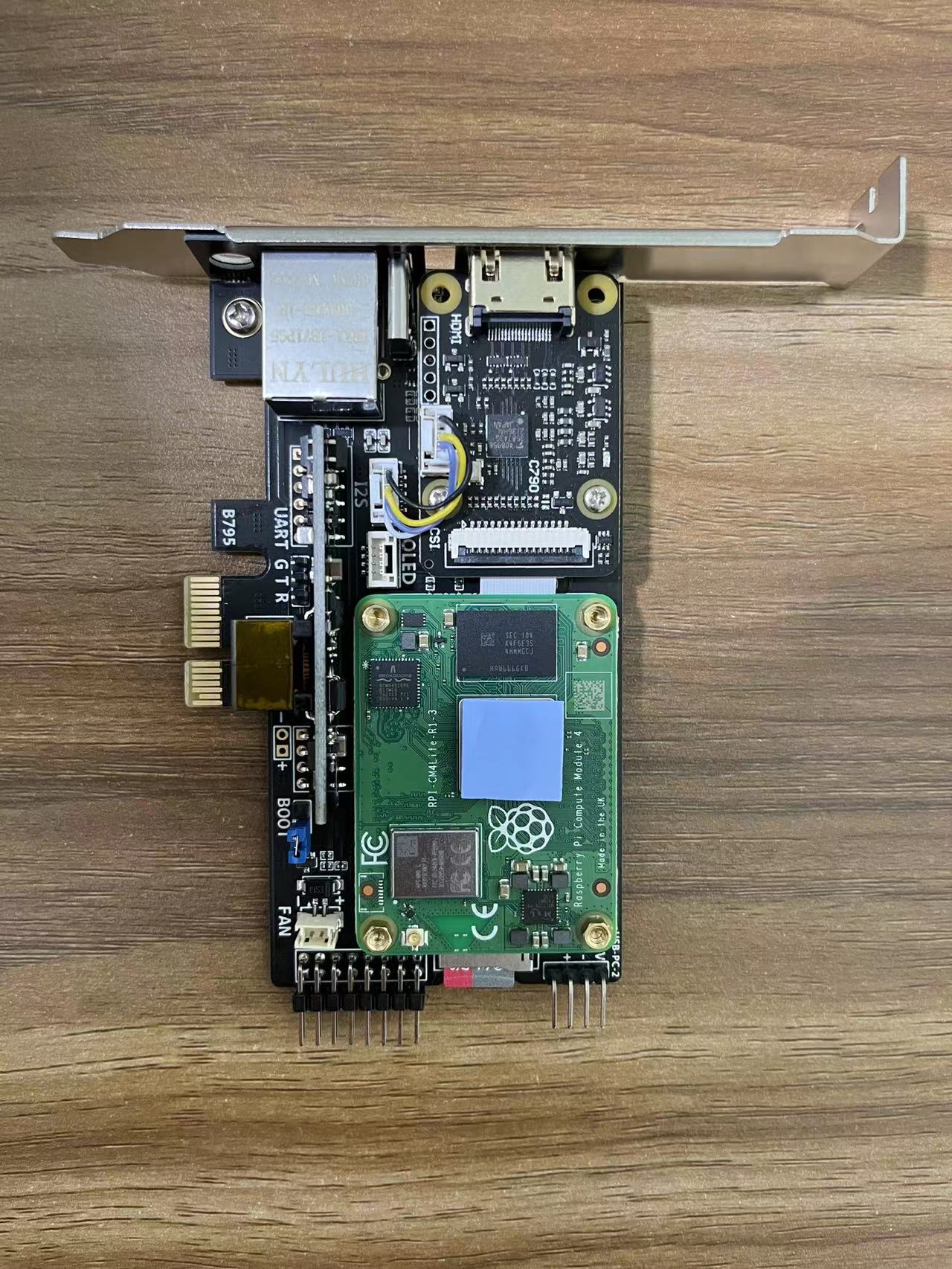
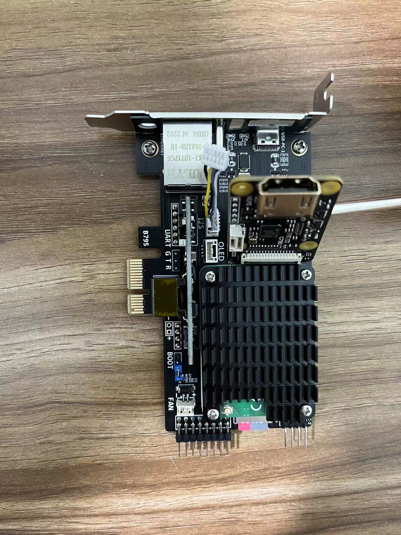
The main device installation is complete.
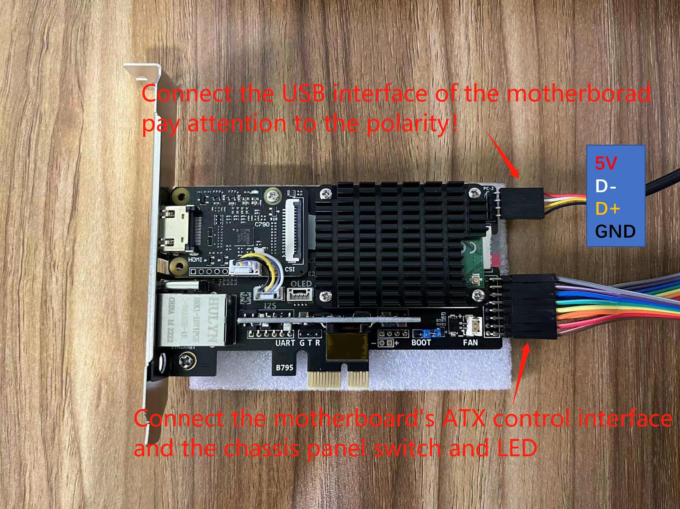
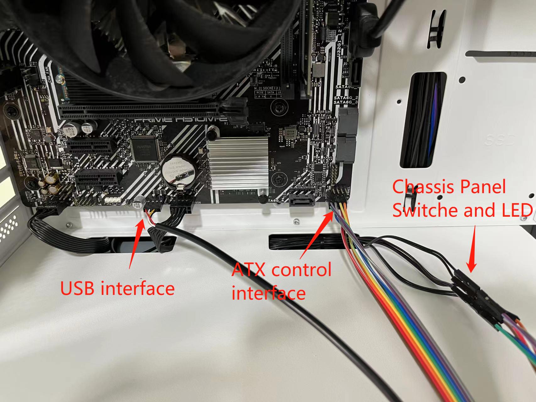
3. Connect USB and ATX
The motherboard used in this article is Asus H520M-E, the interface definition of different motherboards may be different, please refer to your motherboard manual.
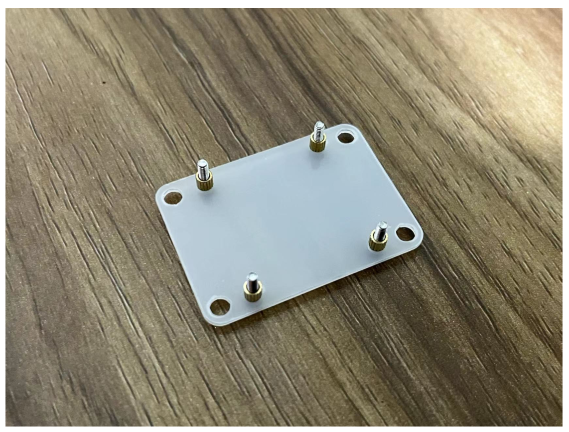
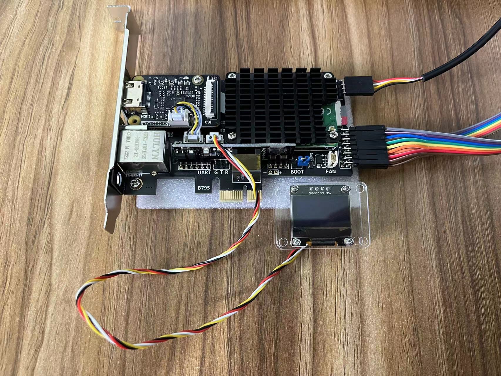
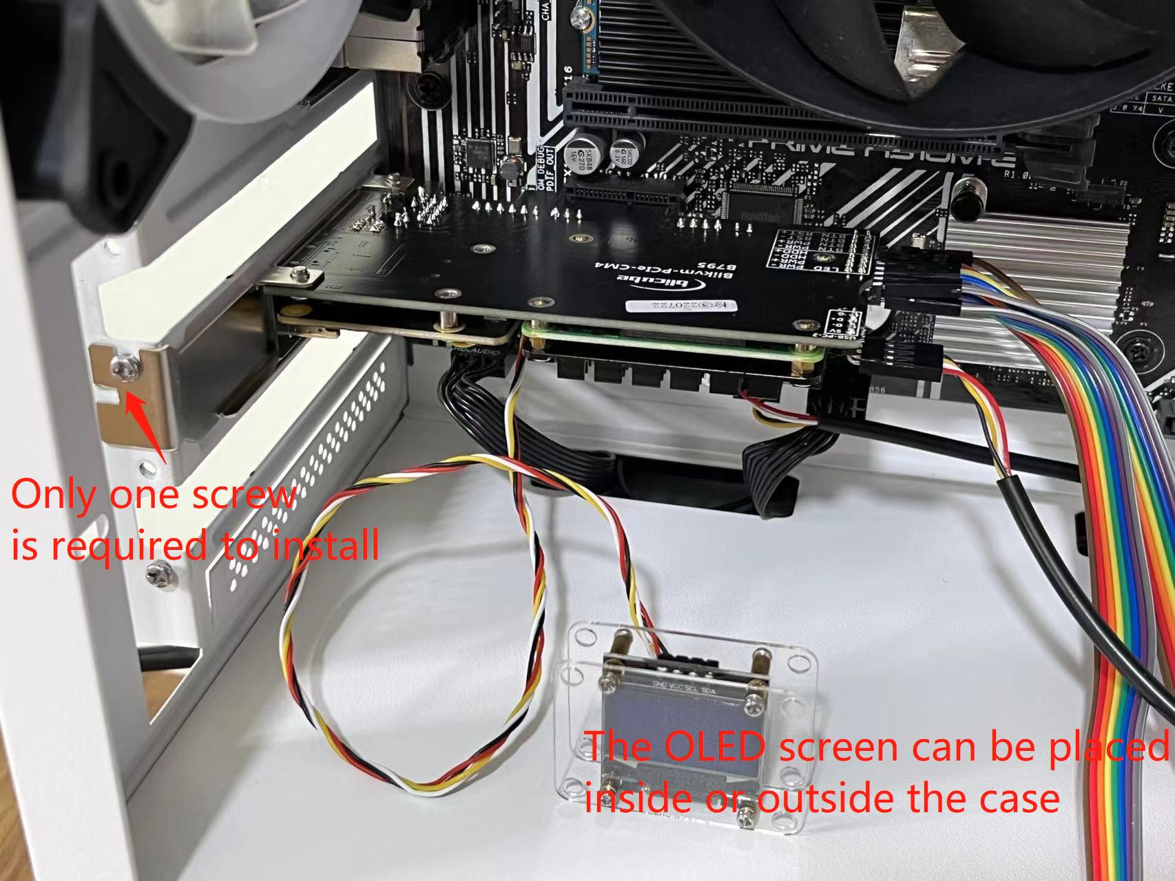
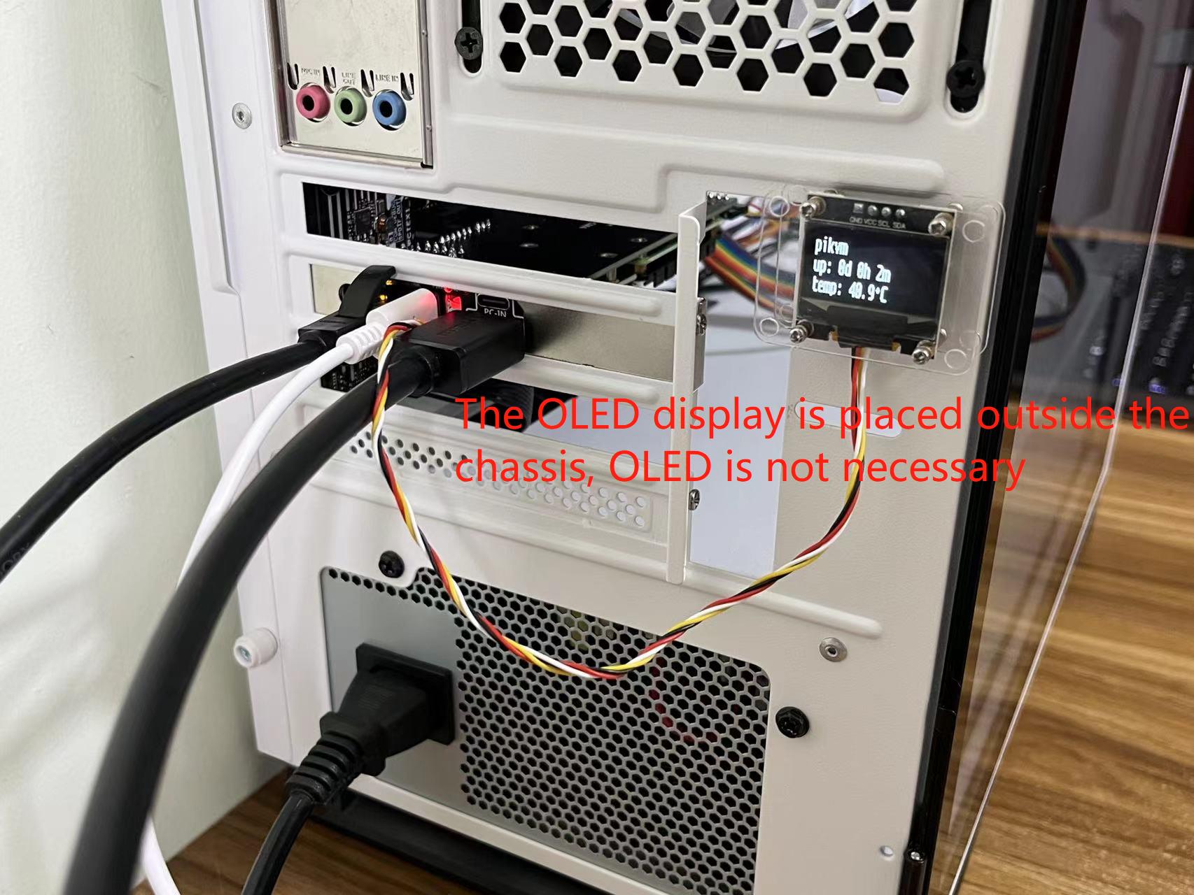
4. Connect OLED
The OLED you received does not have a bracket installed. Please refer to the picture for installation. In addition, OLED support is made of acrylic material, which needs to be used after removing the protective film on the surface.
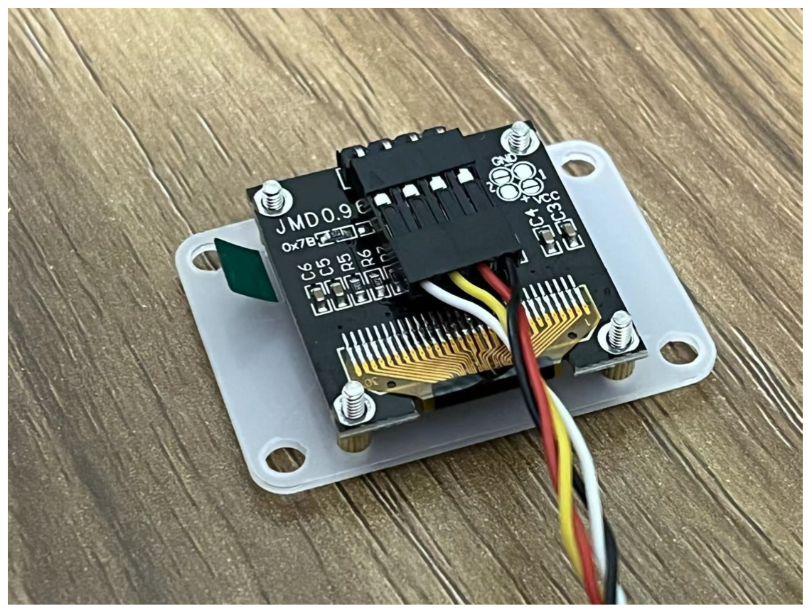
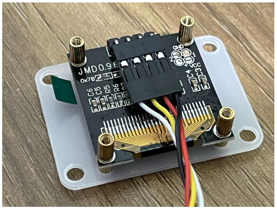
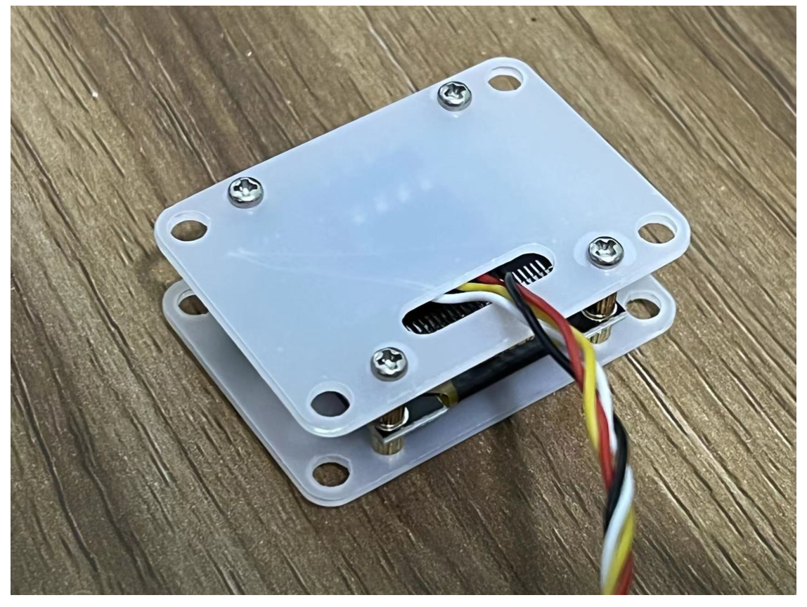
The above is the installation steps, and the effect of not tearing the film is as follows. In actual use, please remove the protective film.
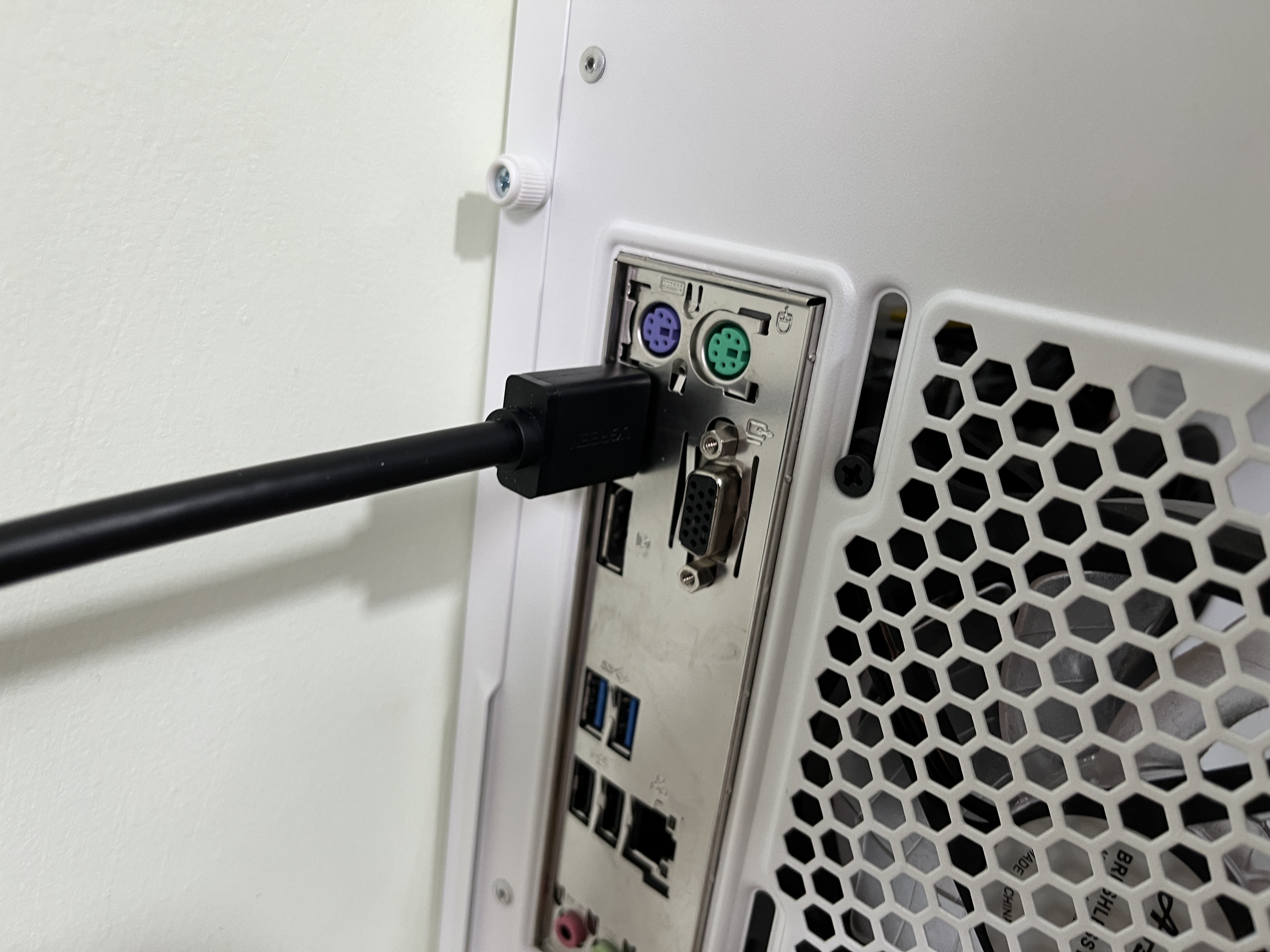
5. Connect the HDMI cable
Connect the HDMI output port of the computer directly to the HDMI IN port of the product with an HDMI cable. The HDMI pass-through EDID emulator is not necessary! If your computer does not output the correct HDMI format, plug the HDMI pass-through EDID emulator into the HDMI output port of the computer. This allows you to configure a fixed HDMI output format on your computer.
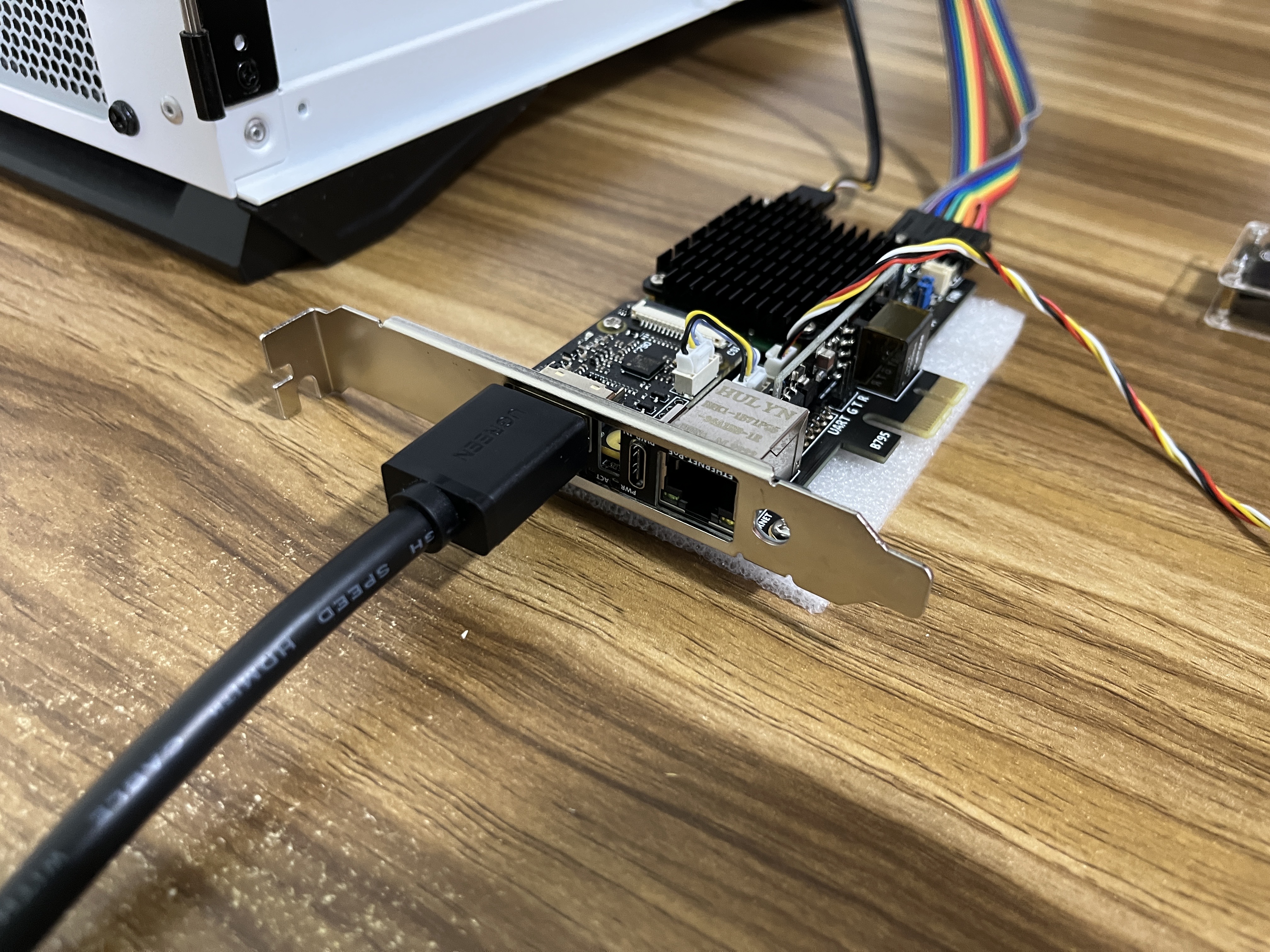
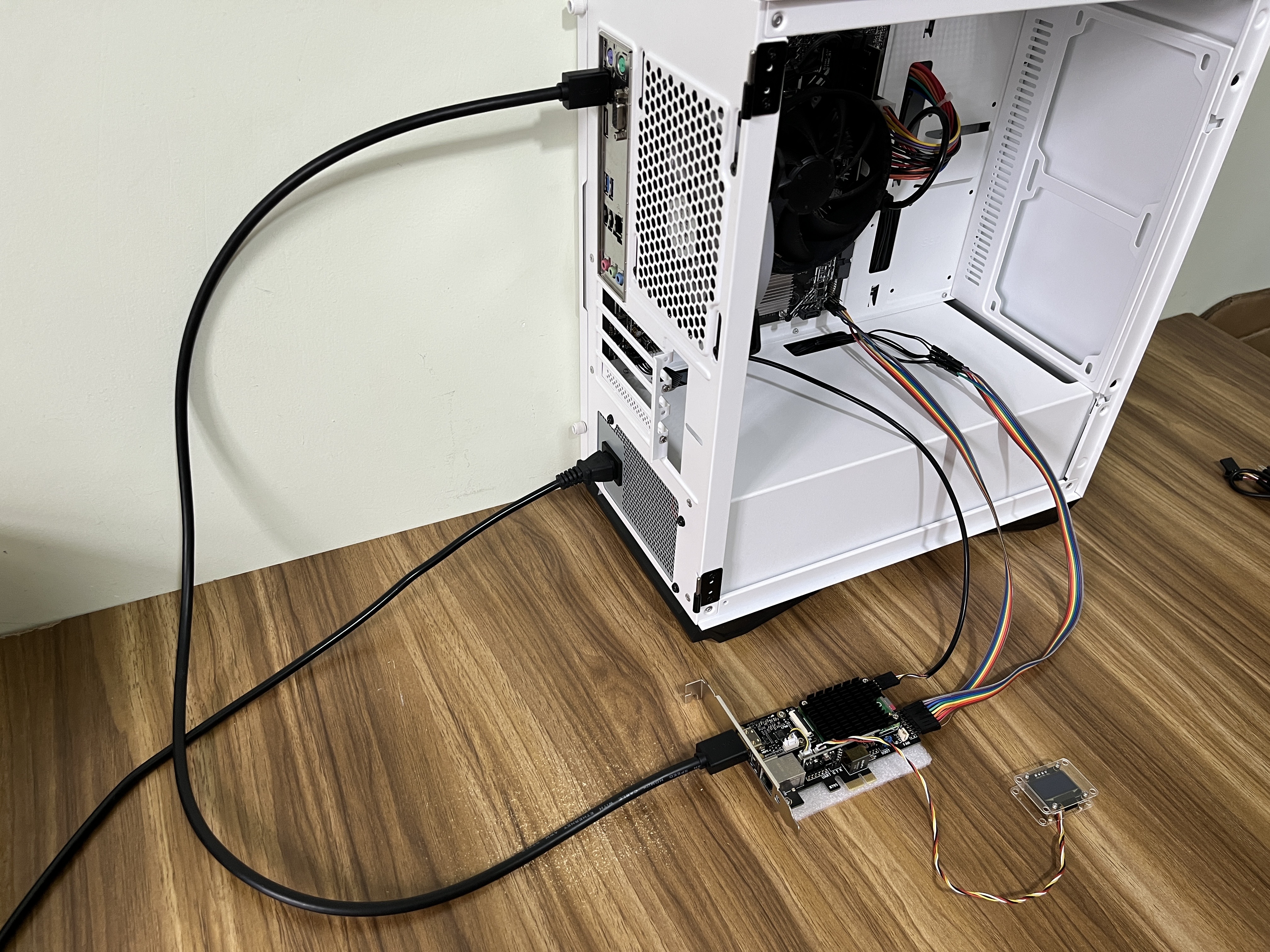
6. Connect the network cable
Gigabit Ethernet port standard: IEEE 802.3af PoE input voltage:37v-57v.
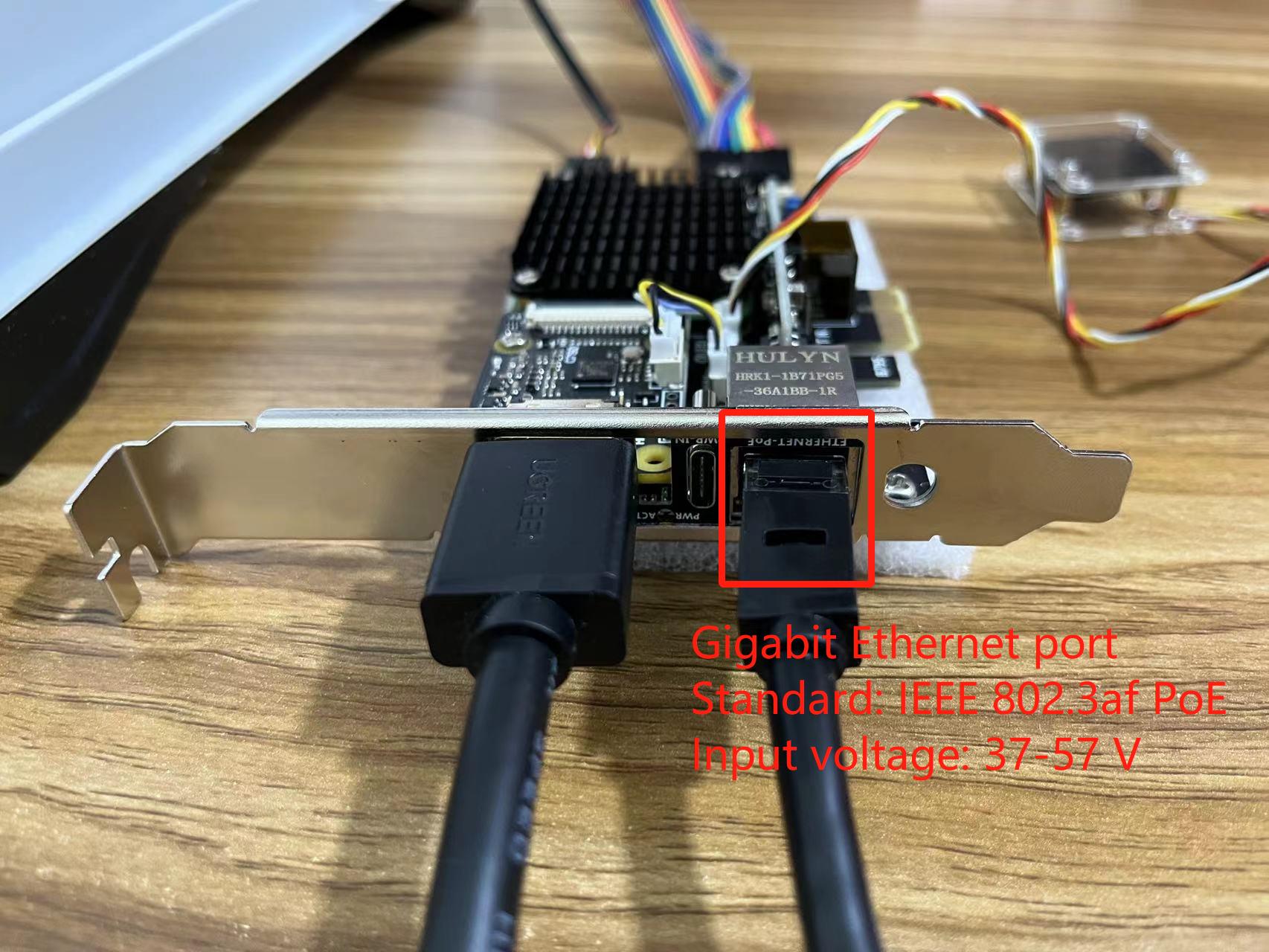
When using PoE power supply, there is no need to connect the PWR-IN port.
7. Connect PWR-IN
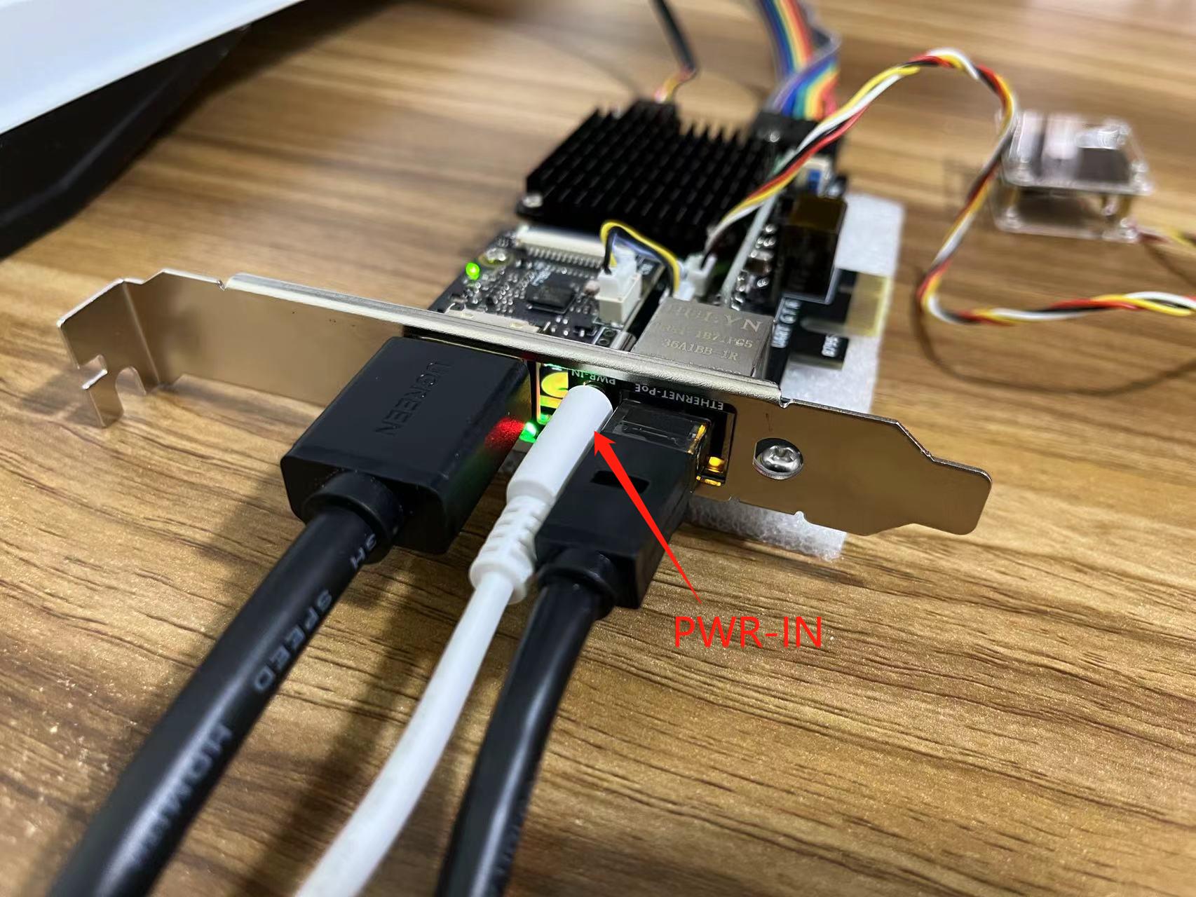
When not using PoE power supply, connect the PWR-IN port to a standard 5V/3A USB power supply.
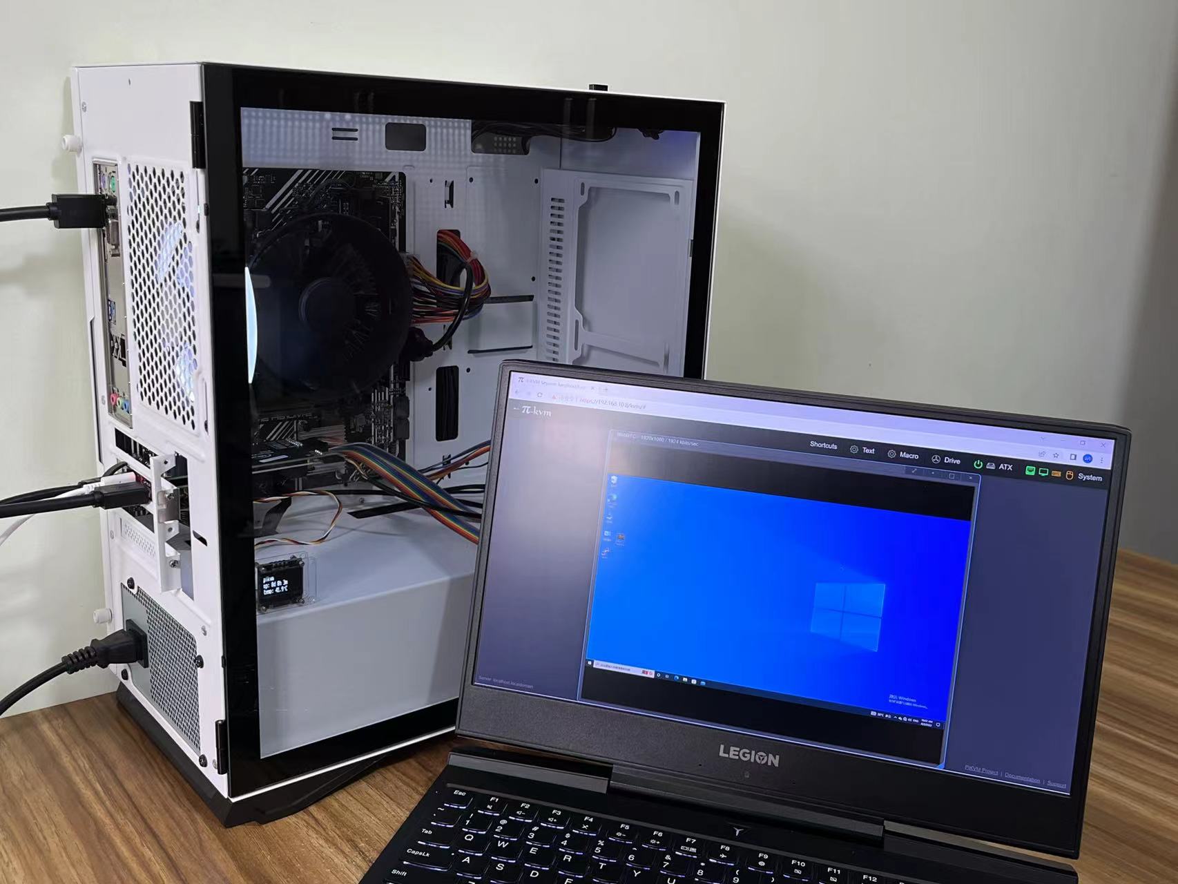
8. Test
OLED screen showing device IP and other information.
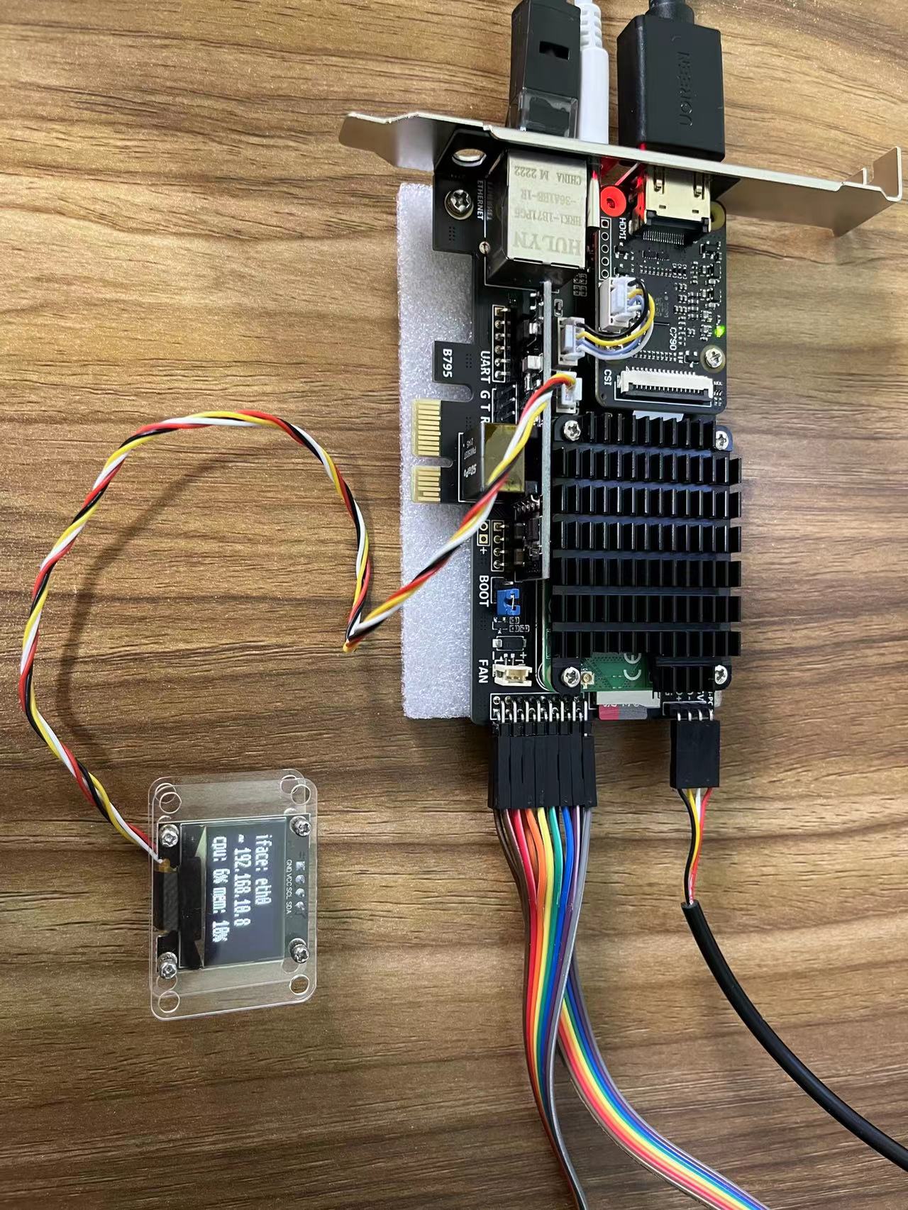
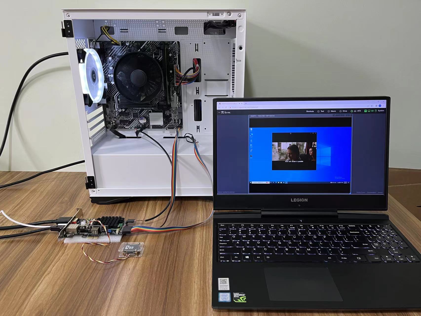 Access the IP address in browser. After passing the test, install the product into the computer case.
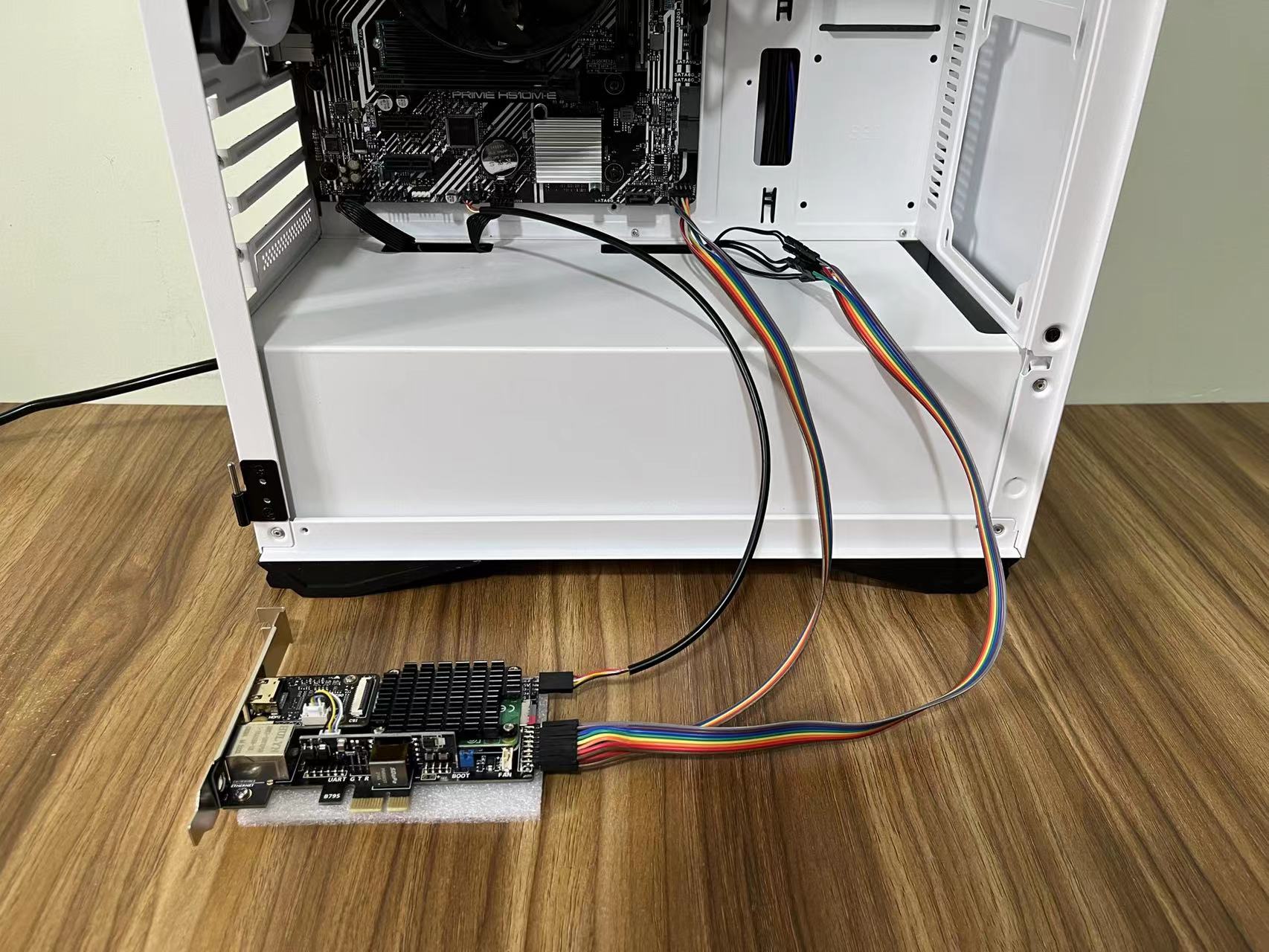
9. Install the product into the computer case
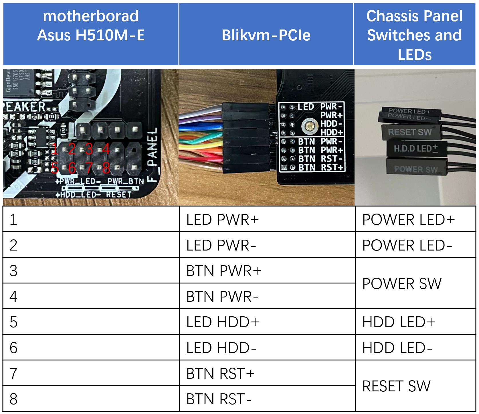
Disconnect power and wiring, install the product on the motherboard, and reconnect the cables after installation is complete. The color of ATX cable received in different batches may be different. Please directly refer to the pin definition for connection
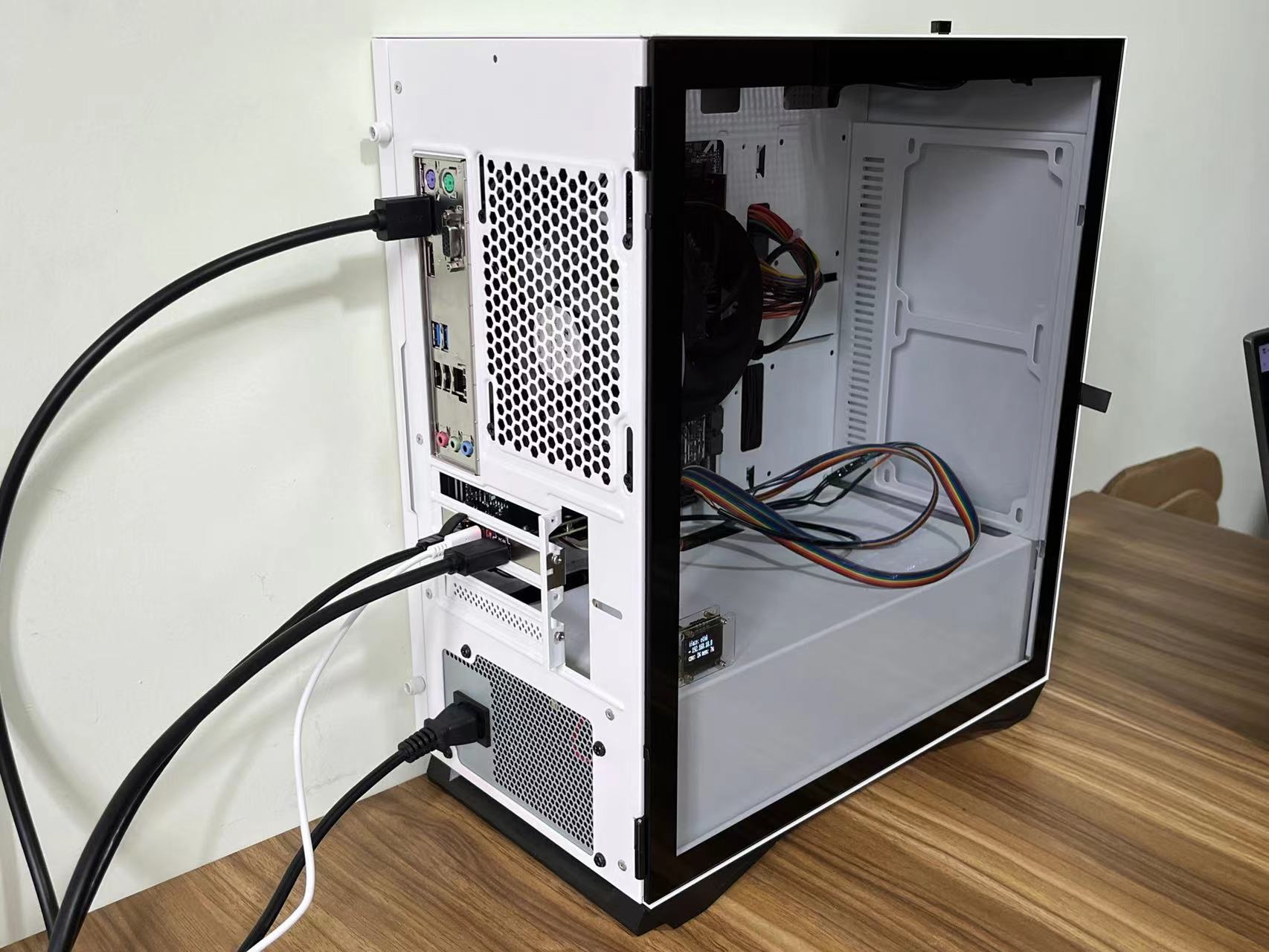
Enjoy!
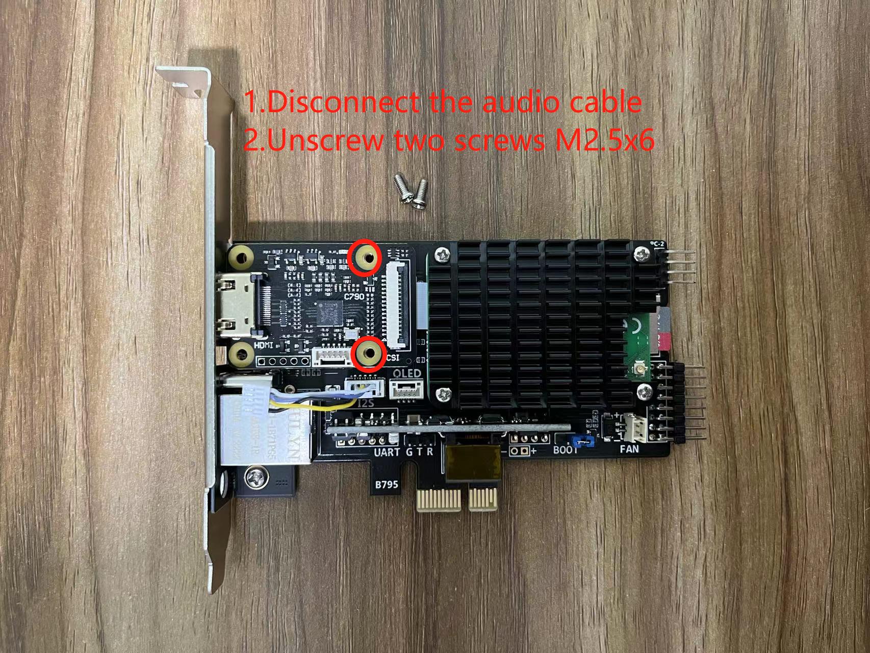
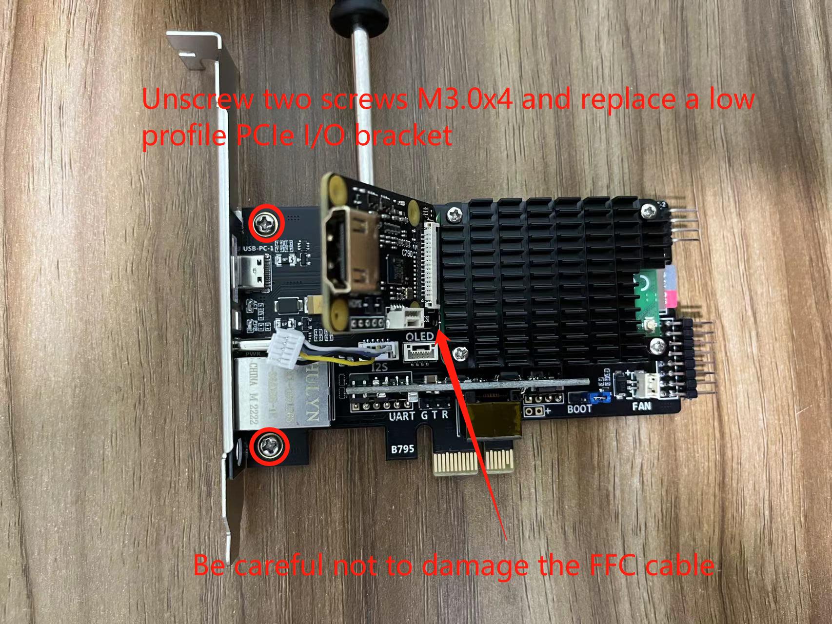
Appendix 1. Install a low profile PCIe I/O bracket
Note
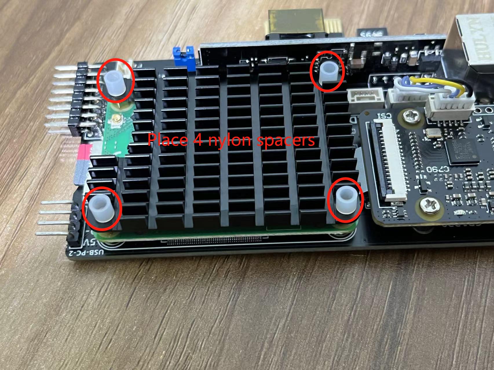
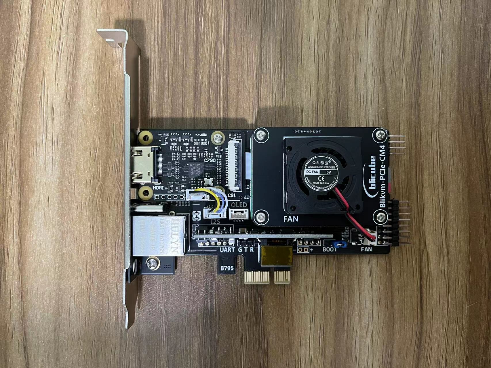
Appendix 2. Install the cooling fan
Usually the metal heatsink is sufficient, the cooling fan is not necessary.
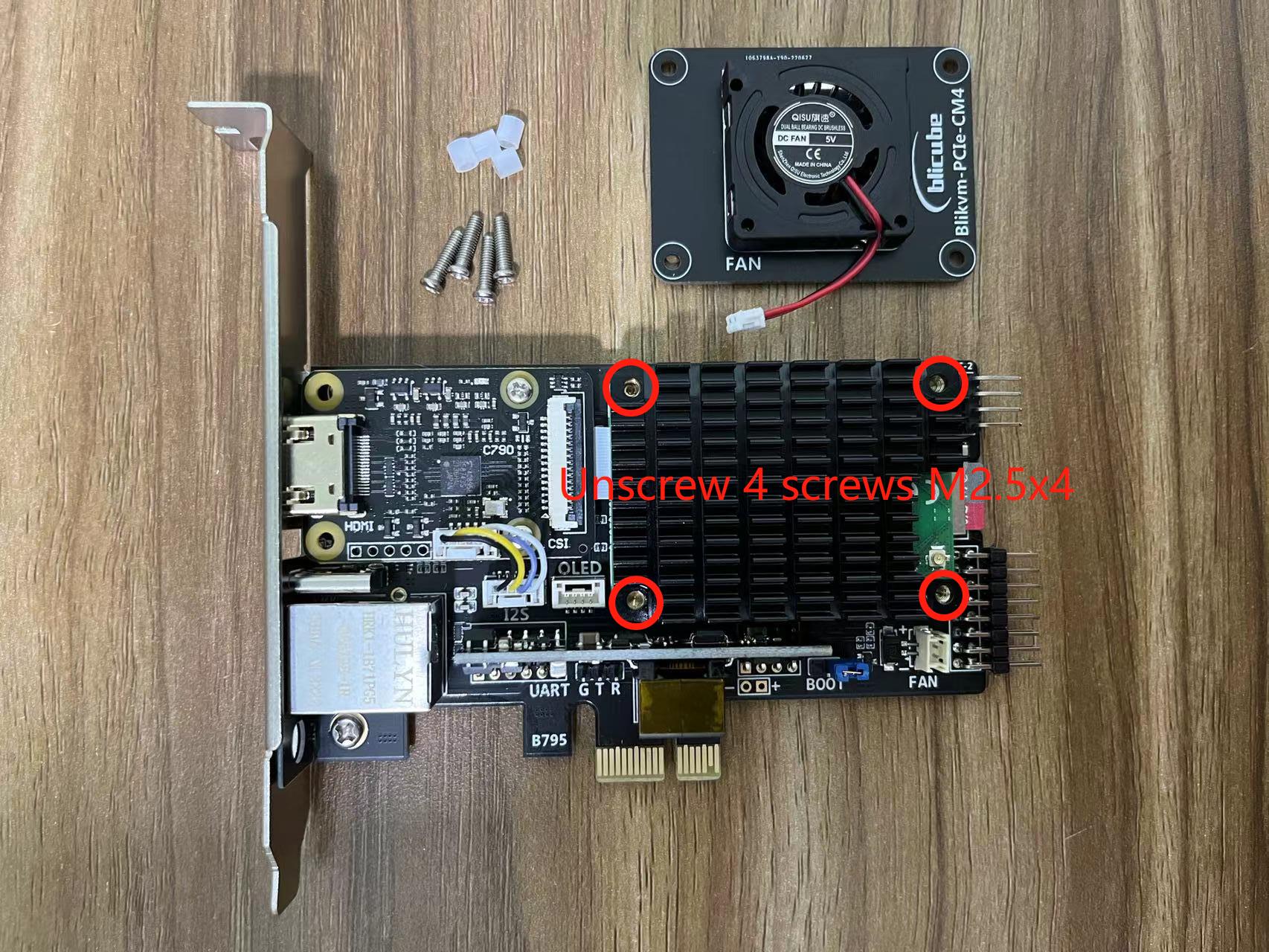
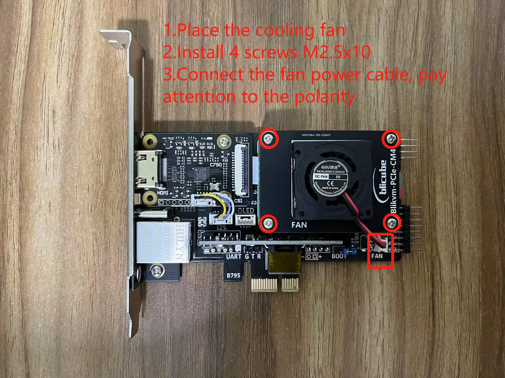
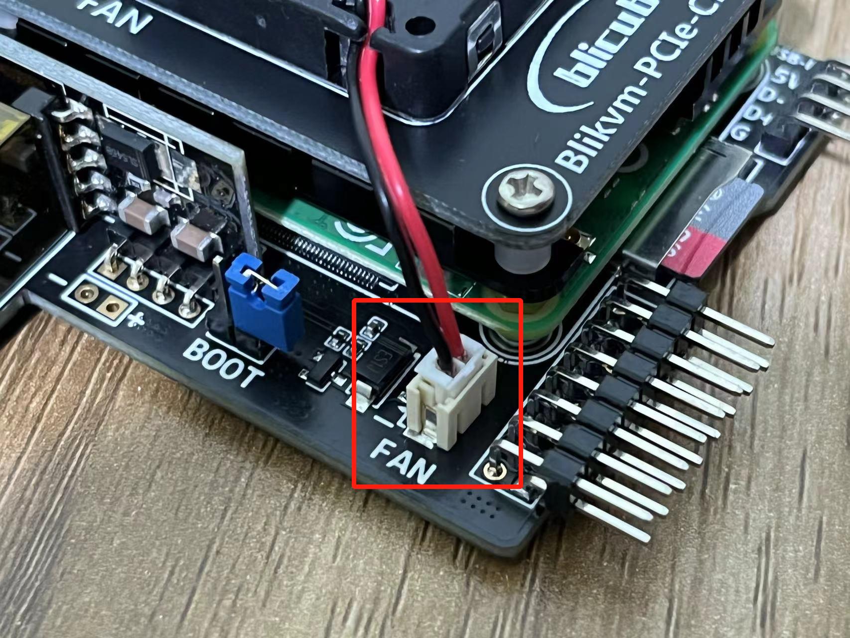
The cooling fan is controlled by CM4 via GPIO12.
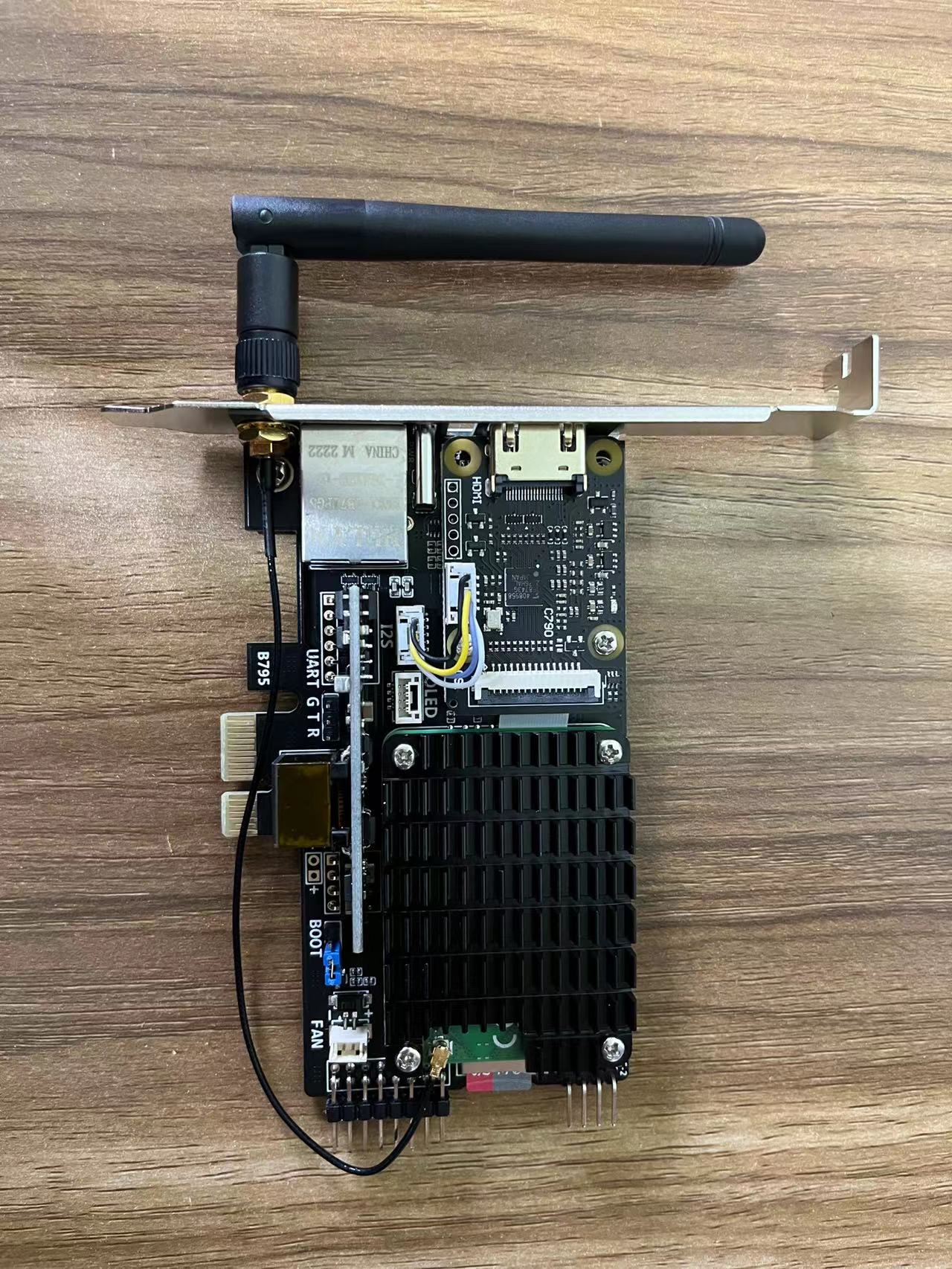
Appendix 3. Install wifi antenna
Note
Created: August 8, 2022